Overview

A custom-designed and programmed card based on the ATTiny85 microprocessor capable of running basic programs in C++, powered by a 3v CR2032 battery. Code and technical documentation is in my Github.

Programs and Libraries Used

EasyEDA, Arduino IDE (C++) using ssd1306

Summary

This was my first PCB design I have created. Based on the ATTiny85-20SU with 8kB of program storage and 512B of SRAM, I planned on making a unique business card that I could give out to show my skills in hardware and software design, while still being configurable in the future. I first ran into a problem with library compatibility, as the library I originally planned on using [Tinky4kOLED] did not work, so I had to find different lightweight libraries to get it to work. I also had a restriction of 3 analog IO pins and 2 digital pins. 2 of the analog pins were used by the I2C bus for the OLED, leaving me with 3 IO pins for 4 buttons. I decided to use one of the analog pins as a button-based voltage divider, which came with its own set of problems such as needing to calibrate each card individually due to different tolerances in manufacturing. The last 2 digital pins were used for LED's. After creating a schematic based on a working breadboard prototype, I ordered 5 boards to test the quality of the PCB fabrication and SMD assembly, which came out as expected. After soldering the rest of the SMD components and the through-hole components, the sketch and calibration went smoothly, and produced a card that I am proud of creating and handing out to those I'm interested in networking with.

Afterthoughts

After ordering my first batch, I optimized the traces to make the PCB look more visually appealing. Ordering additional SSD1306 displays also showed me that the reset button was not necessary, and I had originally received a faulty batch. I only ordered 5 PCB's originally for testing, but now I know that the design works, I plan on using black PCB's and doing some SMD soldering myself.

Link to the code repository

Overview

A purpose-designed longboard sourcing parts and assembling electronics together to create 2 custom electric longboards for less than $650 CAD each including shipping with plenty of battery capacity

Programs Used

Onshape, Cura

Design Decisions

Living about a 30-minute walk from school, I wanted a convenient way to get to school that is more reliable than taking the bus. A bike would be a hassle to bring around and lock up as I wasn't sure about how safe my new school would be, and any other electric scooters/longboards were quite expensive at around $1000 USD for a decent option that could be used for grocheries going uphill. I decided to make a longboard, which would be lighter and more portable than a scooter, plus I have seen previous videos of people creating their own. I wanted something that would be powerful enough to do a decent amount of uphill, have as much mileage as most other products on the market, and have a easily hot-swappable battery system for future expansion. I wanted it to also be used in the rain, so water resistance would be important.
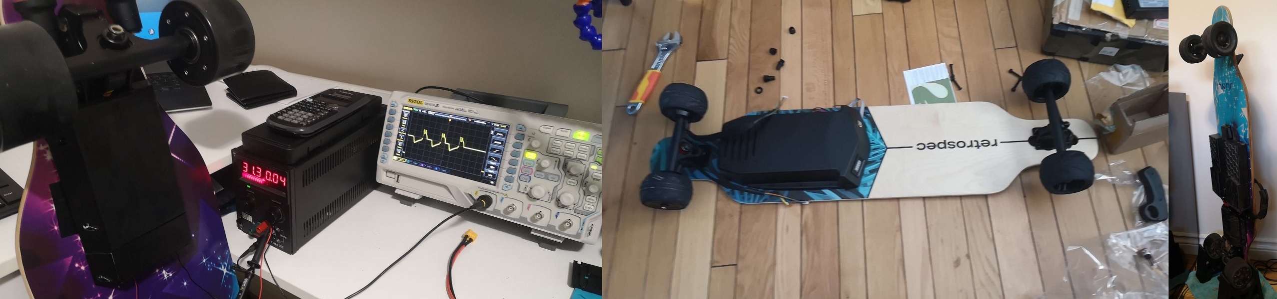
Sourcing Parts

I began sourcing the parts for my board. I sourced some standard hub wheels, but I also got some rubber wheels for the rain thats not factored into the $650 total above, but I figured it'd be useful when the time came for it. The parts took about a month to arrive where I would mount the $200 wheels, $80 electronic speed controller (ESC) and remote combo, some risers, $100 worth of 21700 instead of 18650 batteries for extra capacity and 2 battery management systems (BMS) for each of the battery packs onto a entry-level $100 longboard. This was after I spent about 3 months wondering why my original battery pack didn't arrive due to customs issues, so I had to resort to building my own battery pack.

Design Iterations

I 3D printed every custom component of my board, from the battery housing to controller housing to mud cover mounts. A few components went through several iterations: The battery locking mount and the controller housing. Since I was using this board in the rain, quite a bit of mud would get into the mechanical components of the lock, which would prevent it from unlocking. I decided to go with a simple spring-operated slide mechanism instead of a more complex and delicate solution involving a v-shaped rail to translate vertical to equal horizontal motion. The controller housing and battery box was originally one large box, but after the original battery failed to ship, I made them seperate modules. I initially went with hot glue to seal the wires in, but eventually switched to grommets for better reliability and maintenance. I also switched from PLA to PETG for better durability as the mounting holes on the box were breaking off easily. I also had to change designs completely from a cup design to a fully enclosed box, as water was seeping in from the sides due to inadequate water sealing. The power switch and battery indicators were mounted on the rear wheels, but due to shorter wire lengths, had some trouble and after some wear-and-tear, the wires broke. The board didn't need those parts as it would turn off automatically and turn on when pushed in addition to the remote having a battery indicator for the board as well.

Failures

During a ride in light snow, one of the rubber wheels shorted the ESC MOSFETs, causing one of the MOSFETs to blow up and turn into an expensive smoke machine. That destroyed a $80 controller and one of the $200 pair of hub motors. I also had an XT60 connector for the batteries, but corrosion commonly affected its performance so I switched to deutsch automotive connectors for its current rating and water resistance. Corrosion was a big factor in a lot of design problems, so I began moving away from steel hardware to stainless steel nuts, bolts, and screws. Fortunately, one of the components yet to fail is the battery, as the only repair I had to make was to re-solder one of the BMS balance charge leads that likely fell off due to vibration and repair one of the nickel strips connecting the battery cells that burned off likely from corrosion and the high-current power draw.
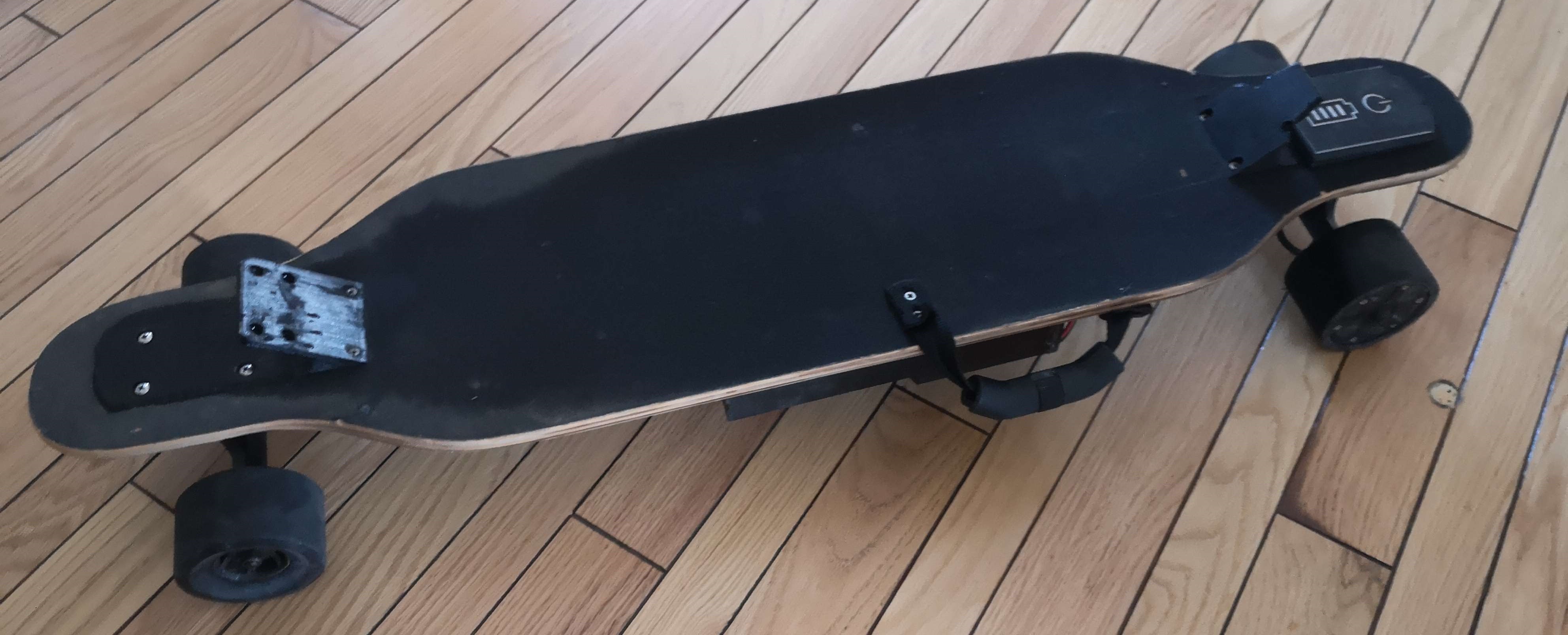
Afterthoughts

After using this for a year, there were a lot of design changes I had to make but has served me well in getting me to school and for making shopping trips a lot easier. A friend of mine also wanted one, so I helped design and build another longboard for him, except I realized that the batteries I got for them were not rated for high discharge, which meant any trips uphill, even at a 5 degree incline, caused the board to stall within a few seconds. Things I would change for next time are better wheels since polyurethane wheels dont ride smoothly on sidewalks or broken roads, better water-resistance designs, and maybe a battery system rated for more cycles.

Link to the CAD files
Link to locking latch CAD files

Overview

A 3D printed shelving unit with RGB LED's for time

Programs and Libraries Used

Arduino IDE (C++) using FastLED and ESP8266 Wireless Libraries

Summary

A version of another project created by DIYMachines on Youtube that I altered to support more lighting effects and customization. Hardware-wise, this project is quite similar as they use the same 3D STL files, but the software has been created from scratch to support web-server control. I programmed multiple lighting effects that the original project did not include such as solid segments, gradients, fire, rain, and rainbow, with these effects also applying to the spotlights, background, and clock. In the image above, I applied a blue to purple background with a solid clock and spotlight pattern. More pictures are available in my GitHub repository below

Afterthoughts

Many of the drilled holes in this project are not aligned properly, so there had to be a few modifications to remediate this. I am also running this clock on 12v, with a buck converter stepping down the voltage to 5v. Under normal operations, this won't be an issue, but if I fully load the shelf with solid white LED's, this would heat up the buck converters to more than 90 degrees celsius with a heatsink on, so I added more buck converters to share the load. I would have gone with a dedicated LED power supply instead, but concealing that would be much more difficult.

Link to the code repository

Overview

A 272Wh portable power bank capable of delivering up to 1.5A 120v AC

Programs and Libraries Used

OnShape

Summary

With a bunch of spare 18650 lithium battery cells, I wanted to create something that would see more use than behing a shelf ornament. Most USB power banks won't make use of 20+ battery cells, so I decided to instead make a power bank, but to power an AC inverter. I made use of an automotive inverter and some additional electronics such as a battery management system, left over charge ports, high power flip switches, and a battery level indicator to design and build a portable power bank. I made the battery pack and soldered the electronics, then measured out the dimensions to make a custom case to fit all the electronics. Eventually, I was able to create what you see above, which can power my laptop charger if I needed the extra battery life.

Afterthoughts

The USB charge ports on the device charge at a measly 400mA and 1A for each of the charging ports. Plugging in a 3A charger into the AC outlet gives me 1.75A of power, which is quite good since plugging that charger in a regular AC outlet provides the same amount of current. Looking at the waveform in the oscilliscope, I notice that I just get an AC square wave. Performance wise, its reasonable as this would be fine with regular loads that convert AC to DC, but will likely introduce more voltage ripple into the system. If I were looking to redo this project, I'd likely go with a better inverter and power electronics next time around for better USB charging performance.


Overview

A proof-of-concept to display the security flaws of simple RFID and IR authentication.

Programs and Libraries Used

Arduino IDE (C++) using display, communication, and program storage libraries

Summary

At the beginning of my first year in University, I wanted to see how easy it would be to clone the student RFID cards. I was able to identify the cards that they used, and ordered a few specific cards that I needed. The reason why I needed a specific type of card was the important data was stored on the UID portion of the card, which is typically not writable. I came into my first problem, which is finding a way to write to these blocks. I tried modifying the library but none of the methods seem to work. I decided to get everything else working, such as the LCD menu and navigation. I did manage to get reading and storing blocks of data to work, and was able to read the contents of the card on the LCD. Writing to the blocks was possible if they were not on UID sector. Later, I decided to add IR signal cloning as well, which could be stored in EEPROM as well. Saving 4 lines of the signal and repeating it would work for nearly every IR sigal, since IR signals are usually 1 or 2 lines that repeat.

Afterthoughts

My main goal of testing my student-card security did not go as planned to due the use of the UID block. However, I was able to accomplish other tasks I hoped to accomplish, so I would not consider this project to be a complete failure. I do plan on returning to this project to try and write to the UID blocks. I will eventually return to this project and likely use an SD card as storage since EEPROM on the Arduino Nano is extremely limited.


Overview

A USB-shell holding a Teensy 3.6 as a keylogger

Programs and Libraries Used

Arduino IDE (C++) using USB host and SD Libraries

Summary

This is the third version of the original code I had, which was based on someone's repository using a Teensy 3.6 as well. In this version, I completely rewrote all the logic in order to maximize compatibility as much as possible, while mimicking the original keystrokes as much as possible. The main issue with the previous versions is how the USB host treats modifier keys, such as Ctrl, Shift, Alt, etc. Due to the fact that they are not recognized as keys themselves, they do not trigger the onPress() functions I had previously relied on. This will not work for workflows other than word processors such as Excel, video-editing, file-selecting, or any other use that would require the use of shift or ctrl for any functions. After using a different onRawPress() function and modifying the USBHost_t36 library, I was able to get this code to work nearly flawlessly on my third revision.

Afterthoughts

The profile of this device is quite large, which would make it harder to conceal. I figured there are a very small group of people who would check their keyboard inputs, which makes this concern non-critical. This project was created as a proof-of-concept, so I do not have much intentions of using this device on the field. In the future, if I do plan on using this on the field, I would implement wireless logging capabilities that would make things more convenient.

Link to the code repository

Overview

A general purpose Discord bot for administration, games, and image manipulation

Programs and Libraries Used

Python 3 using Discord.py, Pillow, Numpy, Scipy, and other image manipulation libaries

Summary

This bot was a rewrite of my original version I had made that had used a deprecated version of Discord.py. This version was made to expand my knowledge of using Discord's Python API as well as asynchronous programming. This was my first introduction into advanced Python concepts with object-oriented programming, classes, async/await functions, so most of the programming done here was not my best programming. Nonetheless, I was able to get this bot up and running to work on image manipulation, general administration/moderation, and some games such as Connect 4 and Chess.

Afterthoughts

Not too long after I was into this project, Discord-Slash was released, implementing a new way to write commands with their own command decorators and error handling. I figured I would complete this project and if I needed to update my bot in the future, I would implement Discord-Slash's API into the new version. As of now, I am content with how this bot is set up.

Link to the code repository

Overview

A secure (for IoT standards) HTTPS login server to control a relay that can remotely turn on my computer from anywhere in the world with internet connectivity.

Programs and Libraries Used

Arduino IDE (C++) using ESP8266 WiFi libraries and a Raspberry Pi 3B running NGROK to create a semi-private HTTPS webserver

Summary

After deciding that I would be moving across Canada to study, I still wanted to be able to access the processing power of my desktop computer at home, without needing to ship a heavy full-sized metal ATX case to the other side of Canada. With an ESP-01 I had, I programmed a simple lightweight login webserver to trigger one of the ESP01's IO pins. That pin is then fed to a transistor, switching a 5v signal to a relay that can short the power switch pins on my motherboard. As the ESP-01 runs on 3.3v logic and the relay works best on 5v, I used a voltage regulator to switch 5v USB power to 3.3v, and used 3.3v logic to control the relay. Once I soldered the required connections on a prototype board, I just needed to figure out how to implement an HTTPS webserver that I can access. I found out about ngrok, which can tunnel a port through my router's firewall such that I can access my login website from anywhere in the world. Being an IoT device, I knew security would be an issue. I blocked off the HTTP server ngrok created, as well as implemented some delay if the password is inputted incorrectly to prevent brute-force attacks. I can also change the URL of the webserver if necessary. I also made sure the relay's wiring to the computer was made in parallel to the case's power switch such that both power switches can be used.

Afterthoughts

The weakest point of this implementation would be the hole ngrok tunnels through the router's firewall. I am unsure to what extent how secure ngrok is, but I also added some measure to protect against any security flaws I could forsee. Unless HTTPS encryption were to be broken or an exploit is found in the browser's implementation of a pop-up login, I would consider this to be a fairly secure implementation of a IoT remote switch

Link to the code repository

Overview

An implementation of long-distance radio communication between Arduino's.

Programs and Libraries Used

Arduino IDE (C++) using SPI libraries for sensors and a LoRa library to interface with the hat

Summary

In Western Engineering Rocketry, I was tasked with designing a long-distance communication system using LOng-RAnge radio (LoRa). With this, I was responsible for determining what data to send from the rocket to the ground station, and how that data is transmitted. I am also responsible for the frame design of the LoRa packet, which means that I was in charge of designing how each byte is sent and received between the Arduino's. LoRa currently has a maximum of 255 bytes that can be sent in a single message, so I decided against using ASCII strings to transmit data. All the data will be broken into bytes, which will be encoded into a char array to be decoded by the ground station back to the respective data types according to the frame headers and identifiers.

Afterthoughts

More libraries and code will be implemented as the number of sensors I have increase. The packet information could have been more modular and support error correction using Hamming codes.


Overview

A basic implementation of periodic snapshots that can be used for time-lapses or surveillance

Programs and Libraries Used

Arduino IDE (C++) using image, file system, and RTC libraries

Summary

Based on the ESP32 Cam Webserver example, I streamlined the code to disable WiFi and store the frame buffers into the SD card. I also implemented a deep-sleep feature to minimize power usage on idle. Due to the fact that the flash LED is hard-wired to one of the SD card's data pins, covering it up with electrical tape should suffice if flash is not needed. Due to the current implementation of the SD library, only the first 4GB of the SD card can be used, though capacities above 4GB are still functional. Even with this restriction, some configuration of delays and resolution can allow for the camera to last a few days, and about 4 hours on a 2s delay 1080p picture.

Programming this camera was another project in-itself, where I needed a separate FTDI programmer due to the fact that the camera does not include one on itself. The board allows for an FTDI programmer (red board above) to be slotted in, and a switch to pull GPIO 0 to GND for programming mode, or floating for operating mode. The additional pin on the side of the FTDI programmer allows for 5v power, while still maintaining a 3.3v logic for the microcontroller. This is to prevent brownouts during uploading and overall stability of the programmer. Moreover, the layout of the programming board has been designed for easy access to the RESET pin underneath the ESP32 Cam, which needs to be pressed whenever code is uploaded to the board.

Afterthoughts

This project was more of a trial and learning experience. I initially planned to have a couple of these set up, but I eventually decided not to due to time constraints. This project did teach me about how to manage frame buffers and applying various effects onto them, learning how modifications to white balance and gain affect the ending picture.

Link to the code repository

Overview

A bot that can generate fake or use real emails and passwords to fill a phishing site with fake credentials.

Programs and Libraries Used

Python 3.8 using Selenium

Summary

At my university, I get a handful of phishing emails with fake logins hoping to snag passwords and login credentials. A few of my friends fell victim to it, but quickly changed their passwords after realizing. This motivated me to create a bot that would sent fake passwords to these sites so that any victims would be covered with fake credentials, greatly prolonging the time it would take to validate real credentials and provide time for the victim to change their credentials, or even spoiling the entire database causing them to discard the data. My current use of the bot uses real Western University emails and real passwords from password breaches, including the commonly used password list: rockyou.txt. The bot can then modify the emails to partially mask the real email, and sends in a fake password from my list of over 14.4 million passwords. The email list only consists of @uwo.ca emails, as most of the phishing emails are directed towards Western students. The bot then sends these fake credentials every 1-5 seconds, and repeating the process until I stop the script or it reaches a limit I set myself. The use of Selenium allows for an easier UI to monitor the process, as well as identifying the ID's of the form elements to modify.

Afterthoughts

Taking into account how some POST requests work, I may implement a proxy service to hide my IP and make it seem as the information is coming from different parts of the world instead of one central IP. If the database does log IP addresses, then my script would only cover the IP's of anyone on my same network. Living on residence, that would cover a majority of first-years who would be more susceptible to these types of phishing attacks, but it would not cover the rest of the students living off-campus or abroad. However, since I don't need a response, I can attempt to alter the sender IP to be from some randomly generated IP.

Link to the code repository